BMW 3: Removing the flat high-voltage connector
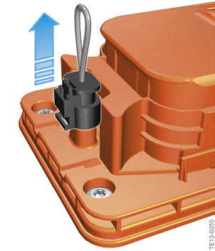
Bridge for high-voltage interlock loop
Before the high-voltage connector can be disconnected, the bridge for the high-voltage interlock loop must first be removed. The bridge closes the circuit of the high-voltage interlock loop in a connected state. The SME and EME control units continuously monitor the circuit of the high-voltage interlock loop. The high- voltage system is only active when the circuit is closed.
If the circuit of the high-voltage interlock loop is interrupted by removing the bridge, the high- voltage system shuts down automatically. This is an additional safety precaution as the Service employee has already switched off the high- voltage system before beginning work.
If the bridge of the high-voltage interlock loop is pulled when the high-voltage system is active, this causes a "hard" opening of the safety contactors. The results may be increased wear or even damage to the contacts.
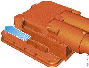
Removing the mechanical locking
Only after the bridge of the high-voltage interlock loop has been removed, can the mechanical locking be moved in the direction of the arrow. The mechanical locking is an element of the high-voltage connector on the high- voltage components (e.g. Electrical Machine Electronics).
By moving the lock in the direction of the arrow the mechanical guide of the high-voltage connector on the high-voltage cable is released which permits the subsequent disconnection.
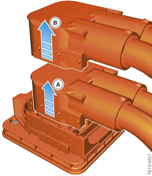
Removing the connector of the high-voltage cable
The connector of the high-voltage cable can now be pulled off in the direction of the arrow.
After pulling off the connector a few millimeters (A) a higher counterforce can be felt.
The connector must then be pulled off further in the same direction (B). Under no circumstances must the connector be pressed back into the socket on the high-voltage component after reaching position (A). This may damage the protective cover at the socket of the high- voltage components.
The high-voltage connector of the high-voltage cables must be pulled out at a right angle in 2 steps in the same direction. Changing the direction of movement when pulling off is not permitted.

The bridge of the high-voltage interlock loop must not be pulled out when the high-voltage system is active.
Proceed in the reverse order when reattaching the high-voltage cable.
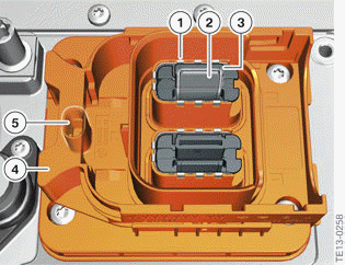
Example of flat high-voltage connector at a high-voltage component
- Electrical contact for shielding
- Electrical contact for high-voltage cable
- Contact protection
- Mechanical locking
- Socket with connection for bridge in the circuit of the high-voltage interlock loop
A contact is available for shielding around each of the two electrical contacts of the high-voltage cables. The shielding of the high-voltage cable (shielding for each cable) is continued into the housing of the high-voltage component.
- The shielding is necessary for the automatic isolation monitoring.
- The shielding contributes to the electromagnetic compatibility (EMC).
In addition, the high-voltage connection provides protection against contact with live parts. The actual contacts are covered in plastic so that nobody can touch them directly. Only when the high-voltage cable is connected is the cover pushed away and the contact established.
READ NEXT:
 Removing the round high-voltage connector
The following figures show the approach for releasing the round high-voltage
connector, as used
for example on the high-voltage cable from the Electrical Machine Electronics to
the convenience
charg
Connection for potential compensation lines
The isolation monitoring determines whether the isolation resistance between
active high-voltage
components (e.g. high-voltage cables) and ground is above or below a required
minimum value. If
the i
Tasks
The Electrical Machine Electronics is made up internally of three
subcomponents:
Bidirectional DC/AC converter
Unidirectional DC/DC converter
EME control unit
The Electrical Machine Electronics
SEE MORE:
Hydraulic braking
G20 PHEV, hydraulic braking
The brake booster is operated via the driver's foot operation, and the brake
actuation is determined by
means of the brake pedal angle sensor.
Depending on the brake pedal angle sensor signal, the valves in the Dynamic
Stability Control (DSC)
are switched so that
Engine compartment
Overview
Jump-starting, positive battery terminal
Oil filler neck
Coolant reservoir, auxiliary cooling
Coolant reservoir, engine
Jump-starting, negative battery terminal
Vehicle identification number
Filler neck for washer fluid
Hood
Safety information
Warning
Improperly executed work in
