BMW 3: Removing the round high-voltage connector
The following figures show the approach for releasing the round high-voltage connector, as used for example on the high-voltage cable from the Electrical Machine Electronics to the convenience charging electronics.
Depending on the installation location, different connectors may be used. They are distinguished by an additional black sliding piece at the connector. The following graphic shows both variants.
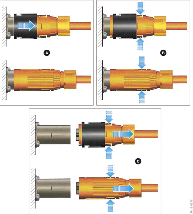
Removing the round high-voltage connector
- The round high-voltage connector is connected to the high-voltage
connection of the corresponding high-voltage component and locked.
In the case of connectors with a black sliding piece, the sliding piece must be pushed to the end position in the direction of arrow. - The two locking elements must be pressed together in the direction of arrow. The mechanical lock of the connector at the connection of the high-voltage component is then removed.
- While the locking elements are being pushed closed together, the connector must be removed in direction of arrow.
When reconnecting the high-voltage cable the locking elements must not be pushed together.
Instead, it is sufficient to slide the connector onto the high-voltage connection of the component and push the sliding piece towards the high-voltage component if needed. Ensure that the locking elements engage ("clicking" noise). In addition, the engaging of the locking elements should be checked by subsequent pulling on the connector.
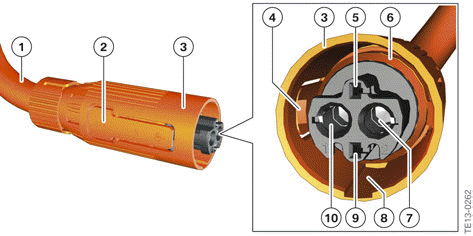
Example of structure of the round high-voltage connector
- High-voltage cable
- Actuation points on locking elements
- Connector housing
- Locking element
- Connection 1 for bridge in the connector
- Connection for shielding
- High-voltage connection, pin 2
- Mechanical encoding
- Connection 2 for bridge in the connector
- High-voltage connection, pin 1
In contrast to earlier high-voltage connectors, the connections for the bridge in the high-voltage connector are not evaluated in the G20 PHEV.
READ NEXT:
 Connection for potential compensation lines
The isolation monitoring determines whether the isolation resistance between
active high-voltage
components (e.g. high-voltage cables) and ground is above or below a required
minimum value. If
the i
Tasks
The Electrical Machine Electronics is made up internally of three
subcomponents:
Bidirectional DC/AC converter
Unidirectional DC/DC converter
EME control unit
The Electrical Machine Electronics
DC/DC converter
The DC/DC converter in the Electrical Machine Electronics of the G20 PHEV is
able to adopt the
following operating modes:
Standby (also in the event of a component fault or short circuit, powe
SEE MORE:
Route
Concept
The route criteria can be individually adjusted.
The settings are stored as standard and automatically
applied to new destination guidances.
Set route criteria
1. Press the button on the
Controller.
2. Move the Controller to the right.
3. "Settings".
4. "Route settings".
5. Select the
Refueling
Follow the following when
refueling
General information
Follow the fuel recommendation prior to refueling.
When refueling, insert the filler nozzle completely
into the filler pipe. Lifting up the fuel pump nozzle
during refueling causes:
Premature switching off.
Reduced return of the fuel vapors
