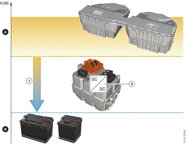
BMW 3: DC/DC converter
The DC/DC converter in the Electrical Machine Electronics of the G20 PHEV is able to adopt the following operating modes:
- Standby (also in the event of a component fault or short circuit, power electronics off)
- Buck mode (energy flow to the low-voltage side, converter adjusts voltage on low-voltage side)
- Discharging the high-voltage link capacitor (interlock fault, accident, request from master).
The DC/DC converter is in "Standby" mode when the Electrical Machine Electronics is not in operation. This is the case when the EME control unit is not supplied with voltage due, for example, to a terminal status. But also if there is a fault, the EME control unit prompts the DC/DC converter to assume "Standby" mode. In this operating mode there is no energy transfer between the two vehicle electrical systems and they remain galvanically separated.
Buck mode (step-down) is the normal operating mode when the high-voltage system is active. The DC/DC converter transfers electrical energy from the high-voltage electrical system to the 12 V vehicle electrical system and assumes the function of the alternator in a conventional vehicle. The DC/DC converter must reduce the varying voltage from the high-voltage electrical system to the voltage in the low-voltage vehicle electrical system. Here the voltage in the high-voltage vehicle electrical system depends on the state of charge of the high-voltage battery unit, for example.
The voltage in the low-voltage vehicle electrical system controls the DC/DC converter so that the 12 V battery is optimally charged and sets a voltage of approximately 14 V depending on the state of charge and the temperature of the battery. The continuous output power of the DC/DC converter is approximately 2.4 - 2.8 kW (temperature-dependent).
Operating principle of the DC/DC converter
- Voltage level of the high-voltage vehicle electrical system
- Voltage of the low-voltage vehicle electrical system, approximately 14 V
- Buck mode (step-down)
- DC/DC converter in the EME
The technology of the DC/DC converter in the G20 PHEV would also enable the operating mode "Boost mode", like the DC/DC converter in the F04. However, this operating mode is not used in the G20 PHEV. Charging of the high-voltage battery unit of the G20 PHEV is thus not possible using energy from the 12 V vehicle electrical system.
When shutting down the high-voltage system, the system must be discharged to a safe voltage of <60 V within five seconds. The DC/DC converter has a discharge circuit for the link capacitors.
First of all, the discharge circuit tries to transmit the energy stored in the link capacitors to the low- voltage vehicle electrical system. If this does not lead to a sufficiently quick reduction of the voltage, the discharging is accomplished via an active resistor. This way the high-voltage electrical system is discharged in less than 5 seconds. For safety reasons there is also a so-called passive discharge resistor (switched in parallel). This enables a reliable discharge of the high-voltage electrical system if the first two measures do not work for discharging due to a fault. The period up until the discharge to a voltage below 60 V is then longer and amounts to a maximum of 300 s.
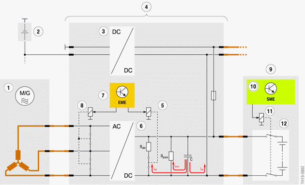
Discharge of the high-voltage link capacitor
- Electric motor
- 12 V vehicle electrical system
- DC/DC converter
- Electrical machine electronics
- Relay (for active discharging of the capacitors)
- Bidirectional DC/AC converter
- EME control unit
- Relay (for short-circuit of the coils of the electrical machine)
- High-voltage battery unit
- SME control unit
- Electromechanical switch contactor
- Cell modules
C - Link capacitor
Rpass - Passive discharge resistor
Ract - Active discharge resistor
The temperature of the DC/DC converter is measured using a temperature sensor and monitored by the EME control unit. If the temperature exceeds the permissible range despite cooling using the coolant, the EME control unit reduces the power of the DC/DC converter to protect the components.
READ NEXT:
 Power electronics for activation of the electrical machine
The power electronics for the activation of the electrical machine are mainly
made up of the
bidirectional DC/AC converter. It is a pulse converter with a 2-pin DC voltage
connection and a 3-phase
A
High-voltage power management
The power management for the high-voltage vehicle electrical system includes
two subfunctions: one
for driving and one for charging mode.
In driving mode, the energy flows from the high-voltage batt
Voltage supply for other high-voltage consumers
The Electrical Machine Electronics supplies voltage not only to the
electrical machine. The
convenience charging electronics are directly connected with the Electrical
Machine Electronics and
ensure
SEE MORE:
Technical data
The following table provides an overview of the technical data of the G20
PHEV 330e compared with
the G20 330i and the F30 PHEV 330e.
* Values may increased, depending on the equipment.
Equipment
The G20 PHEV and G20 differ not only in the technical data but also in the
range of optional
eq
Selector lever positions
Drive mode D
Selector lever position for normal vehicle operation.
All gears for forward travel are activated automatically.
R is reverse
Engage selector lever position R only when the
vehicle is stationary.
Neutral N
The vehicle may be pushed or roll without power,
for instance in vehicle washes i
