BMW 3: Low-voltage connections
In the low-voltage connector at the Electrical Machine Electronics the following lines and signals are combined:
- Terminal 30 from the hybrid power distribution box
- Terminal 30 from the front left power distribution box
- Terminal 30C (terminal 30 crash signal)
- Ground
- FlexRay bus system
- PT-CAN bus system
- K-CAN 5 bus system
- Input and output of the circuit of the high-voltage interlock loop (EME control unit evaluates the signal and initiates a shutdown of the high-voltage system in the event of an interruption to the circuit. Redundancy of battery management electronics (SME) )
- Actuation of the shutoff valve in the vehicle interior
- Activating the electrical vacuum pump
- Evaluation of the rotor position sensor at the electrical machine
- Evaluation of the temperature sensor at the electrical machine
- Intelligent battery sensor of auxiliary battery (LIN bus).
The Electrical Machine Electronics is connected to the 12 V vehicle electrical system (terminals 30 and 31) via two separate low-voltage connections and lines with large cross-sections. Via this connection the DC/DC converter in the Electrical Machine Electronics provides the entire 12 V vehicle electrical system with energy. These two lines are connected with the Electrical Machine Electronics via a screw connection.
The following graphic summarizes the low-voltage connections of the Electrical Machine Electronics in the form of a simplified wiring diagram:
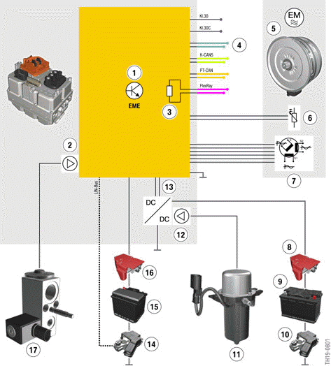
G20 PHEV, low-voltage connections of the Electrical Machine Electronics
- Electric Motor Electronics (EME)
- Output stage for activating the combined expansion and shutoff valve
- Terminating resistor, FlexRay
- Signal lines of the high-voltage interlock loop
- Electrical machine (entirety)
- Temperature sensor
- Rotor position sensor
- Safety Battery Terminal (SBK)
- 12 V battery
- Intelligent Battery Sensor (IBS)
- Electrical vacuum pump
- Output stage for the activation of the electrical vacuum pump
- Unidirectional DC/DC converter
- Intelligent Battery Sensor (IBS2)
- Additional 12 V battery
- Safety Battery Terminal 2 (SBK2)
- Combined expansion and shutoff valve (interior)
READ NEXT:
 High-voltage connections
At the Electrical Machine Electronics, there is a total of three high-voltage
connections to connect the
lines for other high-voltage components. The connections for the electric A/C
compressor and
High-voltage cables
The high-voltage cables connect the high-voltage components and are
identified by orange cable
sleeves. The manufacturers of hybrid cars have agreed on a uniform
identification of the high-voltage
c
Removing the flat high-voltage connector
Bridge for high-voltage interlock loop
Before the high-voltage connector can be
disconnected, the bridge for the high-voltage
interlock loop must first be removed. The bridge
closes the circuit
SEE MORE:
Widgets in the instrument
cluster
Concept
Displays for specific functions can be displayed
in the tachometer in the instrument cluster.
The following displays can be selected:
Current entertainment source, e.g., radio.
Torque and power.
Trip data.
Efficiency display.
Selecting
Continue to press the button on the turn signal
Electric A/C compressor
Electric A/C compressor (EKK)
Signal connector
Low pressure line (gaseous refrigerant at low temperature and low
pressure)
High-voltage connector
High pressure line (gaseous refrigerant at high temperature and high
pressure)
Electric A/C compressor (EKK)
The electric A/C compressor is a
