BMW 3: High-voltage cables
The high-voltage cables connect the high-voltage components and are identified by orange cable sleeves. The manufacturers of hybrid cars have agreed on a uniform identification of the high-voltage cable with the orange warning color. An overview of the high-voltage cables used in the G20 PHEV is provided here.
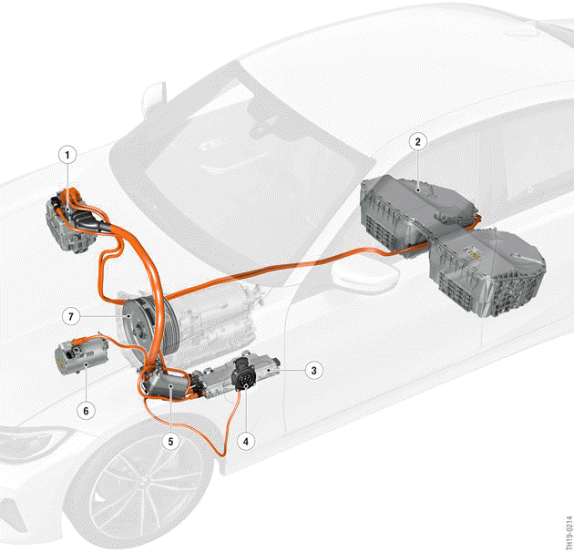
G20 PHEV, high-voltage components and high-voltage cables
- Electric Motor Electronics (EME)
- High-voltage battery unit
- Convenience charging electronics (KLE)
- Charging socket
- Electrical heating
- Electric A/C compressor (EKK)
- Electric motor

High-voltage cables must not be repaired. In the event of damage, the high-voltage cable must be fully replaced!
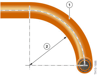
Bending radius of a high-voltage cable
- High-voltage cable
- Bending radius must be greater than 70 mm
The high-voltage cables must not be excessively bent or kinked The bending radius must not be less than 70 mm Excessive kinking/bending of the high-voltage cable may result in damage to the cable shielding and thus to an isolation fault in the high-voltage vehicle electrical system.
Work on live high-voltage components is expressly prohibited. Prior to every operation which involves a high-voltage component, it is essential to disconnect the high-voltage system from the voltage supply and to secure it against unauthorized return to service.
- Charging plug is not connected to the vehicle.
- Enter the PARK vehicle condition (e.g. by holding down the media button of the head unit).
- Wait until the vehicle enters "sleep mode" (identifiable by the fact that the START-STOP button is not illuminated).
- Open high-voltage safety connector.
- Secure the high-voltage system against restarting at the high-voltage service disconnect.
- Activate PAD mode (e.g. by operating the START-STOP button three times within 0.8 s).
- Wait until the Check Control message "High-voltage system switched-off" is displayed in the instrument cluster.
- Enter PARK vehicle condition.
READ NEXT:
 Removing the flat high-voltage connector
Bridge for high-voltage interlock loop
Before the high-voltage connector can be
disconnected, the bridge for the high-voltage
interlock loop must first be removed. The bridge
closes the circuit
Removing the round high-voltage connector
The following figures show the approach for releasing the round high-voltage
connector, as used
for example on the high-voltage cable from the Electrical Machine Electronics to
the convenience
charg
Connection for potential compensation lines
The isolation monitoring determines whether the isolation resistance between
active high-voltage
components (e.g. high-voltage cables) and ground is above or below a required
minimum value. If
the i
SEE MORE:
Displays in the instrument cluster
Displays of operating conditions
The hybrid-specific operating states and the state of charge of the
high-voltage battery unit are
displayed in the instrument cluster and, if desired, in the Central Information
Display (CID).
The displays shown below may appear, depending on the driving situation
Last calls
The last outgoing, missed, and incoming calls
are transferred to the vehicle. Depending on the
equipment, the calls are transferred from the
main phone and additional phones.
Displays
1. "COM".
2. If necessary, "Telephone".
3. "Recent calls".
4. The last calls are displayed.
Filtering call list
1
