BMW 3: System wiring diagram
BMW 3 Series G20 (2018-2026) Training manual / Drive Components / Fuel supply / System wiring diagram
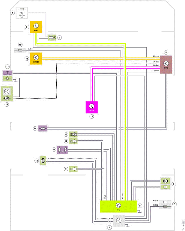
G20 PHEV, system wiring diagram for fuel supply
- Integrated supply module
- Digital Motor Electronics (DME)
- Shutoff valve purge air line (only for US version)
- Body Domain Controller (BDC)
- Fuel filler flap lock
- Power distribution box, rear
- Fuel pump control electronics
- Hybrid pressure refuelling electronic control unit (TFE)
- Fuel tank isolation valve (only for US version)
- Electric fuel pump
- Pressure/Temperature sensor
- Fuel tank isolation valve (only for European version)
- Fuel tank shutoff valve (only for US version)
- Lever sensor for fuel level
- Advanced Crash Safety Module (ACSM)
- Power window motor, driver's side (supply for LED refuelling button )
- Refuelling button
- Instrument cluster (KOMBI)
- Power distribution box, front left
In the event of a crash, the fuel pump control electronics immediately disconnect the power supply to the fuel pump drive. The fuel pump control electronics receive the information for this from the Advanced Crash Safety Module ACSM.
READ NEXT:
 Refuelling
The pressurized fuel tank must be vented before refuelling. To initiate the
refuelling procedure, the
button in the driver's door first needs to be operated. The button is not active
when the vehicl
Introduction
The automatic transmission GA8P75HZ of the G20 PHEV, which is based on the
transmission
introduced in the F07 at the end of 2009 (GA8HP70Z), is also manufactured by ZF.
If you have already take
SEE MORE:
System limits
Certain noises can be detected and may lead
to problems. Keep the doors, windows, and
glass sunroof closed.
Noises from the front passenger or the rear
seat bench can impair the system. Avoid
making other noise in the vehicle while
speaking.
Major language dialects can cause problems
with
Recent destinations
General information
The previous destinations driven to are stored
automatically.
Open the destination from the
last destinations
1. Press the button on the
Controller.
2. "Recent destinations".
3. Select the destination.
Edit recent destinations
1. Press the button on the
Controller.
2. "Recen
© 2019-2026 Copyright www.bmw3g20.com
