BMW 3: Components and their installation location
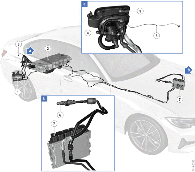
G20 PHEV components of the fuel supply in European version
- Carbon canister
- Pressurized fuel tank (in cast aluminum housing)
- Fuel filler flap with cover
- Fuel tank isolation valve
- Cable for emergency release of the fuel filler flap
- Tank vent valve
- Digital Motor Electronics (DME)
Fuel tank isolation valve
The fuel tank isolation valve is opened to reduce the tank pressure during driving if the system limit is reached. In parked, this is achieved by a mechanical valve which is integrated in the fuel tank isolation valve. It is additionally opened before refuelling to ventilate the pressurized fuel tank.
The fuel tank isolation valve is opened during current supply. In the event of a crash there is no active power supply to the fuel tank isolation valve (it remains closed) and no fault memory entry is set by the TFE. This does not prevent subsequent refuelling of the vehicle or other functions (purging, etc.) as long as the components involved (e.g. pressure-temperature sensor) are undamaged.
Fuel tank non-return valve
The fuel tank shutoff valve is additionally used for US version vehicles. This is necessary to perform legally required tank leak diagnosis. The fuel tank shutoff valve is closed when power is supplied.
Pressurized fuel tank
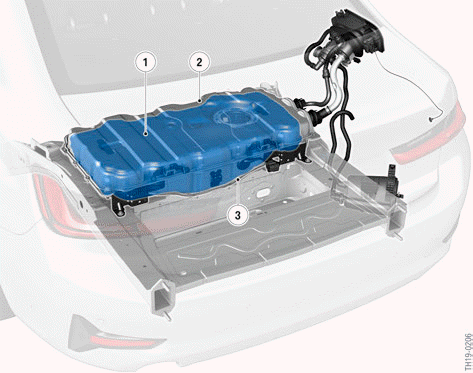
G20 PHEV pressurized fuel tank
- Pressurized fuel tank made from stainless steel
- Cast aluminum upper housing section
- Cast aluminum lower housing section
The G20 PHEV has the high-voltage battery unit in the normal fuel tank packaging space (below the rear seat bench). This has lowered the center of gravity, and the luggage compartment can be used more efficiently (flat loading floor, through-loading system). The pressurized fuel tank with a fuel tank capacity of 40 liters was integrated below the luggage compartment. It is located in a cast aluminum housing which is mounted to the body. The housing improves the body stiffness and crash performance.
READ NEXT:
 System wiring diagram
G20 PHEV, system wiring diagram for fuel supply
Integrated supply module
Digital Motor Electronics (DME)
Shutoff valve purge air line (only for US version)
Body Domain Controller (BDC)
Fue
Refuelling
The pressurized fuel tank must be vented before refuelling. To initiate the
refuelling procedure, the
button in the driver's door first needs to be operated. The button is not active
when the vehicl
SEE MORE:
Destination entry by voice
General information
Instructions for the voice activation system,
see vehicle Owner's Manual.
When making a destination entry by voice,
you can change between voice operation and
iDrive.
To have the available voice commands read
out loud: ›Voice commands‹ or ›Help‹.
Saying the entri
Heat management module
The heat management module replaces the characteristic map thermostat.
Heat management module
Electrical Split Cooling Valve (SCV)
Coolant output towards the coolant pump
Electrical actuator
Rotary valve
A rotary valve inside the heat management module ensures needs-driven cooling
of the var
