BMW 3: Rotor and stator
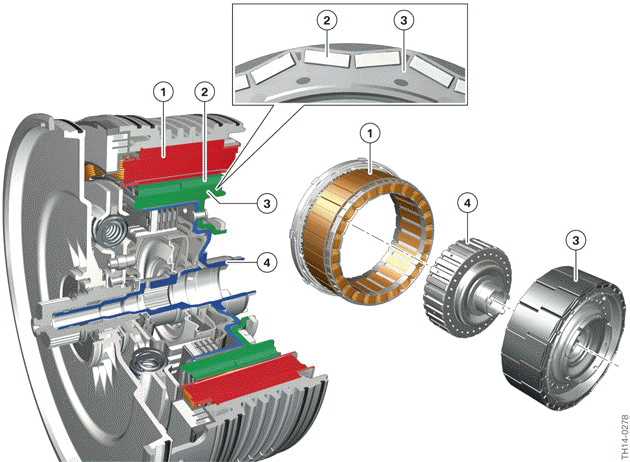
Rotor and stator, electrical machine
- Stator
- Permanent magnets
- Rotor
- Hollow shaft with outer basket of separation clutch
The electrical machine in the G20 PHEV is structured as an inner rotor. "Inner rotor" means that the rotor is arranged with the permanent magnets arranged in a ring shape on the inside. The coils for generating the rotating field are located on the outside and form the stator. The electrical machine has 8 pole pairs.
The rotor is mounted above a flange on the rotor hollow shaft, which is positively connected to the transmission input shaft.
READ NEXT:
 Connections
Connections, electrical machine
Transmission bell housing
Temperature sensor
Coolant ducts
Connection for coolant (transmission oil)
Electrical connection, rotor position sensor
High-voltage c
Sensors
Sensors, electrical machine
Temperature sensor
Rotor of the rotor position sensor
Stator of the rotor position sensor
So that the voltages for the coils in the stator can be correctly calculated
Separation clutch
The G20 PHEV is a Full-Hybrid Generation 4.0 vehicle. In contrast to
generation 2 and 3 hybrid
vehicles, electrical driving is possible in the G20 PHEV at much higher speeds
and with a higher range.
SEE MORE:
Apple CarPlay preparation
Concept
CarPlay allows certain functions of a compatible
Apple iPhone to be used via Siri voice operation
and iDrive.
Functional requirements
Compatible iPhone.
iPhone 5 or later with iOS 7.1 or later.
Corresponding mobile contract.
Bluetooth, WiFi, and Siri voice operation are
activated on th
General information
Video files and, depending on the vehicle equipment,
video DVDs can be played. Sound is
played back through the vehicle loudspeakers.
Settings are stored for the driver profile currently
used.
The video image on the front Control Display is
switched off when a country-dependent speed is
exceeded.
© 2019-2026 Copyright www.bmw3g20.com
