BMW 3: Overview
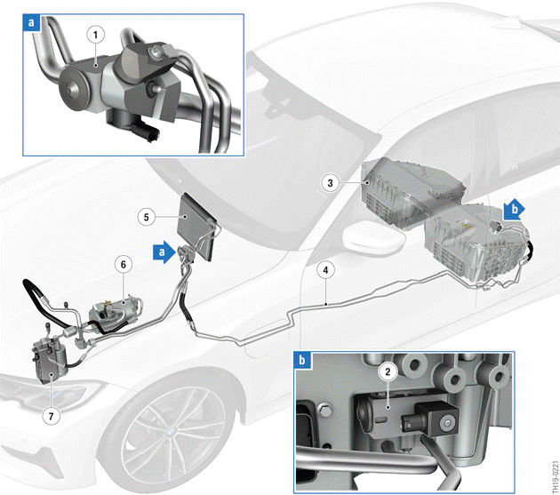
G20 PHEV, system overview of climate control - Installation locations
- Combined expansion and shutoff valve at the evaporator
- Combined expansion and shutoff valve at the high-voltage battery unit
- High-voltage battery unit
- Refrigerant lines to high-voltage battery unit
- Evaporator, passenger compartment
- Electric A/C compressor (EKK)
- Coolant-based air conditioning condenser (coolant-refrigerant-heat exchanger)
Cooling system of the high-voltage battery unit
The high-voltage battery unit is cooled directly using R1234yf . The refrigerant circuit of the air conditioning consists of 2 parallel branches. One for cooling the passenger compartment and one for cooling the high-voltage battery unit. For each branch there is a combined expansion and shutoff valve in order to be able to control the cooling functions independent of each other. The battery management electronics can activate and open the combined expansion and shutoff valve at the high- voltage battery unit by applying voltage. In this way refrigerant can flow to the high-voltage battery unit. The cooling of the passenger compartment is also effected in a condition-based manner. The combined expansion and shutoff valve upstream from the evaporator can also be activated electrically by the EME. The amount of flowing refrigerant is adjusted thermally (depending on the refrigerant temperature) via the expansion valves.
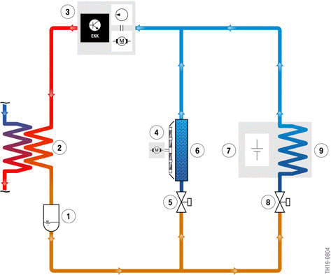
Refrigerant circuit with high-voltage battery unit (simplified illustration)
- Receiver dryer
- Coolant-based air conditioning condenser (coolant-refrigerant-heat exchanger)
- Electric A/C compressor (EKK)
- Blower for passenger compartment
- Combined expansion and shutoff valve, passenger compartment
- Evaporator, passenger compartment
- High-voltage battery unit
- Combined expansion and shutoff valve, high-voltage battery unit
- Heat exchanger
As a result of the pressure drop after the expansion valve, the refrigerant in the lines and coolant ducts of the high-voltage battery unit evaporates. In the process the refrigerant absorbs heat energy from the cell modules or battery cells and cools them. The evaporated refrigerant then leaves the high-voltage battery unit, is compressed by the electric A/C compressor and liquefied in the coolant/refrigerant heat exchanger. Although energy is required from the high-voltage electrical system for this procedure, it is of utmost importance. Only this way can a long service life and a high degree of efficiency of the battery cells be guaranteed.
READ NEXT:
 Functions
The cooling system has 2 operating conditions, which result from its
function:
Cooling OFF
Cooling ON
Cooling OFF operating condition
The "Cooling OFF" operating condition is active when the cell
Introduction
Although the high-voltage battery unit of the G20 PHEV can also be partially
charged by energy
recovery via the electrical machine, the "normal" charging procedure takes place
when the G20
SEE MORE:
Safety belt reminder for driver's
seat and front passenger seat
Display in the instrument cluster
The indicator light lights up and
a signal
sounds. Make sure that the safety belts
are positioned correctly. The safety belt
reminder can also be activated if objects are
placed on the front passenger seat.
Safety belt reminder for rear
seats
General information
Th
Coolant
General information
Coolant consists of water and additives.
Not all commercially available additives are suitable
for the vehicle. Information about suitable additives
is available from a dealer's service center
or another qualified service center or repair shop.
Safety information
Warning
With t
