BMW 3: Operating strategy
The following graphic shows the positions of the rotary valve as the coolant temperature increases:
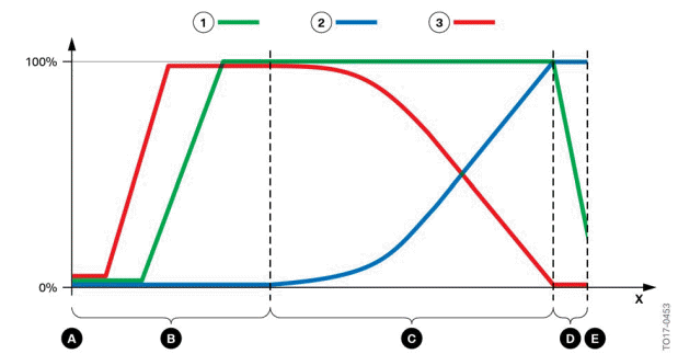
Switching diagram heat management module
0% - Rotary valve closed
100% - Rotary valve open
- Cold start
- Warm-up phase
- Operating temperature
- Transition from normal operation to maximum cooling requirement
- Maximum cooling requirement
X - Rotational angle in angular degrees
- Heater circuit
- Main coolant circuit
- Minor coolant circuit
The openings on the rotary valve vary the cross-sections of the different coolant ducts as a function of the rotational angle of the rotary valve. The following graphics schematically represent the various engine operation phases, from cold start to maximum cooling requirement.
Cold-start phase
Point A in the heat management module circuit diagram designates the cold start with an engine that has completely cooled down.
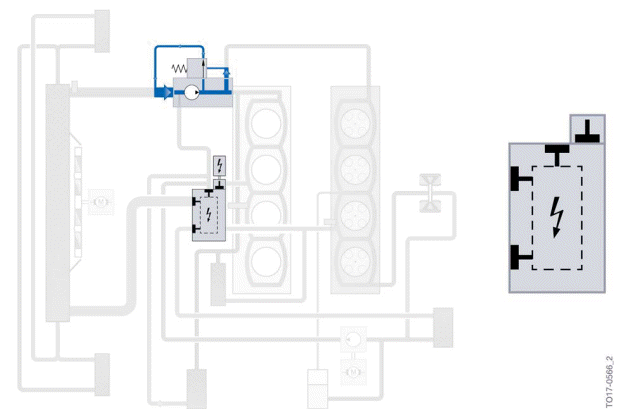
Cold-start phase
In the cold-start phase, the coolant circulates exclusively via a bypass in the coolant pump. The rotary valve in the heat management module closes the coolant lines so that the excess pressure that builds up opens the pressure relief valve in the coolant pump (opening pressure 2.2 bar) and the coolant is recirculated in the coolant pump.
Because the coolant circuits through the exhaust turbocharger and the ventilation line of the cylinder head cannot be closed, a low volumetric flow is returned to the coolant pump here.
Warm-up phase
Area A in the circuit diagram for the heat management module shows the opening angle of the rotary valve in the warm-up phase.
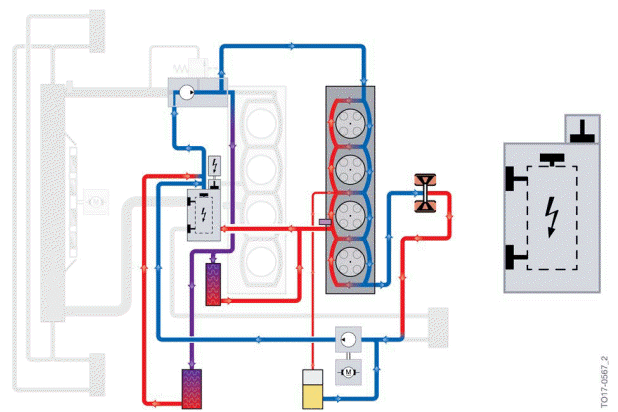
Warm-up phase
In the warm-up phase, the heat management module additionally opens the connection to the heating in addition to opening the bypass line. The coolant flows through the cylinder head, the exhaust turbocharger and the engine oil/coolant heat exchanger. The electrical Split Cooling Valve is closed; no coolant flow through the engine block (Split Cooling).
READ NEXT:
 Operating temperature
The positions of the rotary valve at engine operating temperature are shown
by area C of the heat
management module circuit diagram.
Operating temperature
The graphic shows control with the engine a
Coolant pump
The layout and function of the coolant pump have been revised and adapted to
match the cooling
concept of the B46TU/B48TU engines.
Coolant pump
Pressure relief valve closed (pressure <
Exhaust System
Exhaust turbocharger
Exhaust turbocharger
The exhaust turbocharger can be replaced individually and is exclusively made
of steel. The boost
charge pressure is still controlled by an electrical waste
SEE MORE:
Vehicle apps
Concept
BMW ConnectedDrive Services offer the option
to display information regarding the weather or
sports, for example, on the Control Display using
apps and other functions.
Display BMW ConnectedDrive
Service apps
1. "Apps".
2. "Installed apps".
3. "All services".
4. Select desired app.
5. "F
Activating the voice activation
system
General information
There are various methods for activating the
voice activation feature:
Press the button on the
steering
wheel.
Say the wake word ›Hello BMW‹ or a personal
wake word.
Then say the command. No other commands
may be available. In this case, operate the function
via iDriv
