BMW 3: Heat management module
The heat management module replaces the characteristic map thermostat.
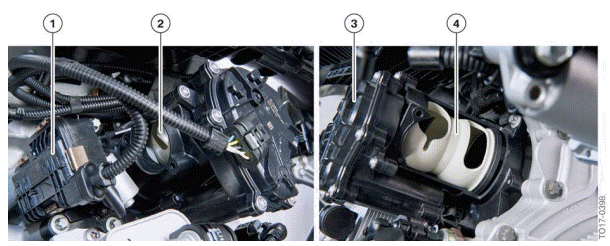
Heat management module
- Electrical Split Cooling Valve (SCV)
- Coolant output towards the coolant pump
- Electrical actuator
- Rotary valve
A rotary valve inside the heat management module ensures needs-driven cooling of the various engine components. The opening cross-sections of the various coolant ducts can be opened or closed variably. A position sensor in the electrical actuator of the heat management module forwards the current position of the rotary valve to the Digital Motor Electronics (DME). The exact position of the rotary valve can thus be determined so that it opens or closes a precisely defined cross-section with respect to the various coolant ducts. Adjusting the cross-sections ideally adapts the flow rates of the coolant ducts connected to the heat management module to the engine operating points. To correctly position the rotary valve, the Digital Motor Electronics (DME) require information including the coolant temperature from the coolant temperature sensor, and the material temperature of the cylinder head from the component temperature sensor .Warm-up and cooling of the engine and the supply to ancillary components can be implemented as driven by requirements, thus optimizing consumption.
READ NEXT:
 Operating strategy
The following graphic shows the positions of the rotary valve as the coolant
temperature increases:
Switching diagram heat management module
0% - Rotary valve closed
100% - Rotary valve open
Cold
Operating temperature
The positions of the rotary valve at engine operating temperature are shown
by area C of the heat
management module circuit diagram.
Operating temperature
The graphic shows control with the engine a
Coolant pump
The layout and function of the coolant pump have been revised and adapted to
match the cooling
concept of the B46TU/B48TU engines.
Coolant pump
Pressure relief valve closed (pressure <
SEE MORE:
Data protection
Data transfer
Concept
The vehicle offers different services, whose use
requires a data transfer to BMW or a service provider.
The data transfer can be deactivated for
some services.
General information
When the data transfer is deactivated, the respective
service cannot be used.
Only make these se
Changing/canceling the
recognition function
If another vehicle key or another digital key is to
be assigned to a driver profile, the current assignment
must be canceled first.
Via iDrive:
1. "CAR".
2. "Driver profiles".
3. Move the Controller to the right.
As an alternative for Steps 1 to 3, the profile
image can be tapped in the top stat
