BMW 3: Equipotential bonding
The low-resistance connection between the housing of the high-voltage battery unit and ground is a crucial prerequisite for the fault-free function of the integrated isolation monitoring. This is why it is important to observe the correct tightening torque for all assembly screws. It is also important to ensure that neither the housing of the high-voltage battery unit nor the body at the respective bore holes/threads is painted, corroded or dirty. The bare metal must be exposed if necessary before the assembly screws can be mounted.

If the low-resistance connection between the high-voltage battery unit and the body ground is insufficient, then a possible isolation fault remains unnoticed and cannot be detected by the isolation monitoring. In the event of a fault, there is the potential danger of an electric shock.
When mounting the mounting bolts and equipotential bonding screws, the exact procedure must be observed:
- Clean contact surfaces and screw hole threads and have them checked by a second person
- Tighten assembly screws to specified torque
- Have torque checked by second person
- Both persons must record this in the vehicle records for the correctness of the version. The "Form for equipotential bonding screw connections" is provided in ISTA application for this purpose.
System wiring diagram
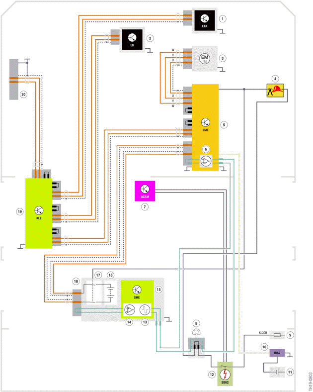
G20 PHEV, system wiring diagram for high-voltage battery unit in the
high-voltage network
- Electric A/C compressor (EKK)
- Electrical heating
- Electric motor
- High voltage disconnect (rescue disconnect)
- Electric Motor Electronics (EME)
- Evaluation circuit for test signal of the high-voltage interlock loop in the Electrical Machine Electronics
- Advanced Crash Safety Module (ACSM)
- High-voltage safety connector ("Service Disconnect")
- Voltage supply for power distribution box, rear right (30B)
- Intelligent battery sensor (IBS2)
- Auxiliary battery
- Safety battery terminal (SBK2)
- Clock generator for the test signal of the high-voltage interlock loop in the battery management electronics (SME)
- Evaluation circuit for test signal of the high-voltage interlock loop in the battery management electronics (SME)
- Battery management electronics (SME)
- Cell modules of the high-voltage battery unit
- Electromagnetic switch contactor
- High-voltage battery unit
- Convenience charging electronics (KLE)
- Charging socket
READ NEXT:
 Monitoring functions
High-voltage interlock loop
The SME control unit evaluates the signal of the high-voltage interlock loop
and checks whether there
is an open circuit with this circuit. In the event of an open circuit
Labels
Three signs are attached to the housing of the high-voltage battery unit: 1
type plate and 2 warning
stickers. The type plate provides logistical information (e.g. part number) and
the key technical
SEE MORE:
Driving style analysis
Concept
The function helps develop an especially efficient
driving style and to conserve fuel.
For this purpose, the driving style is analyzed.
The assessment is done in various categories
and is displayed on the Control Display.
This display will help you adjust your driving style
and save some
Laser high beams
Concept
The range of the high beams is increased and
ensures an even better illumination of the road.
General information
When the high beams are switched-on, starting
with a speed of approx. 37 mph/60 km/h, the laser
high beams in the headlight are automatically
switched on in addition to the LED h
