BMW 3: Overview
With the G20 PHEV the already familiar Generation 4.0 high-voltage battery unit with the designation SP41 is used. The lithium-ion battery has the same basic design as the Generation 3.0 SP06 high- voltage battery unit. The same can be found in the G12 PHEV and also in the G30 PHEV. The most significant change as compared to the predecessor model is that the cell capacity has been increased from 26 Ah to 34 Ah.
The high-voltage battery unit is a high-voltage component
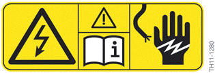
High-voltage component warning sticker
Each high-voltage component has on its housing an identifying label that enables Service employees and vehicle users to intuitively identify the possible hazards that can result from the high electric voltages used.

Only Service employees who satisfy all the prerequisites are permitted to work on the designated high-voltage components: suitable qualifications, compliance with the safety rules, procedure following the exact repair instructions.
The high-voltage battery unit is a complete system, which is made up of the following essential components:
- Cell modules including cells connected in series
- Cell supervision circuits (primary/secondary)
- Safety box
- Control unit for battery management electronics (SME)
- Four-part heat exchanger
- Wiring harnesses
- Connections (electrical system, refrigerant, venting)
- Housing and fastening parts.
The primary task of the high-voltage battery unit is to absorb electrical energy from the high-voltage electrical system, store it and make it available again later as necessary, as well as converting this energy into chemical energy. In addition, it assumes important tasks that contribute to the safety of the high-voltage system, such as the high-voltage interlock loop. The high-voltage battery unit can be charged by brake energy regeneration (energy recovery) and via the external power supply system.
In order to reach the desired electrical range of the G20 PHEV, the energy reserve to be stored must be dimensioned accordingly. This has an effect on the volume and the weight of the high-voltage battery unit. The high-voltage battery unit is installed in the place where normally the fuel tank is located.
The high-voltage battery unit is a complex, high-voltage component: it is imperative to observe the handling instructions and safety regulations. In particular, lithium-ion batteries must not be overcharged or subjected to excessively high temperatures. Otherwise, there is an explosion hazard Work on live high-voltage components is expressly prohibited. Prior to every operation which involves a high-voltage component, it is essential to disconnect the high-voltage system from the voltage supply and to secure it against unauthorized return to service.
- Charging plug is not connected to the vehicle.
- Enter the PARK vehicle condition (e.g. by holding down the media button of the head unit).
- Wait until the vehicle enters "sleep mode" (identifiable by the fact that the inscription in the START-STOP button is not illuminated).
- Open high-voltage safety connector.
- Secure the high-voltage system against restarting at the high-voltage service disconnect.
- Activate PAD mode (e.g. by operating the START-STOP button three times within 0.8 s).
- Wait until the Check Control message "High-voltage system switched-off" is displayed in the instrument cluster.
- Enter PARK vehicle condition.
READ NEXT:
 Technical data
The high-voltage battery unit of the G20 PHEV is manufactured by BMW itself
in Dingolfing /Germany.
The cells of the high-voltage battery unit are supplied by the Korean company
Samsung SDI. T
Equipotential bonding
The low-resistance connection between the housing of the high-voltage battery
unit and ground is
a crucial prerequisite for the fault-free function of the integrated isolation
monitoring. This is wh
Monitoring functions
High-voltage interlock loop
The SME control unit evaluates the signal of the high-voltage interlock loop
and checks whether there
is an open circuit with this circuit. In the event of an open circuit
SEE MORE:
Vehicle apps
Concept
BMW ConnectedDrive Services offer the option
to display information regarding the weather or
sports, for example, on the Control Display using
apps and other functions.
Display BMW ConnectedDrive
Service apps
1. "Apps".
2. "Installed apps".
3. "All services".
4. Select desired app.
5. "F
New schematic diagram
The representation of the individual bus systems and their designations have
been adapted to the
representation and the designation of the ISTA workshop information system.
The following table provides an overview of the previous and the current
representation and
designation:
Bus overview
G2
