BMW 3: Electrical connections
The high-voltage battery unit also has a signal connection, as well as the high-voltage connection.
The high-voltage battery unit is integrated in the refrigerant circuit in order for it to be cooled.
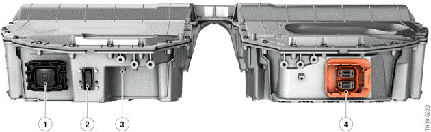
Connections of the SP41 high-voltage battery
- Venting unit
- Signal connector
- Connections for refrigerant lines
- High-voltage connection
The electrical lines (high-voltage and signal connection), as well as the refrigerant lines, can be disconnected without having to remove the high-voltage battery unit.
Low-voltage connection
There is a signal connection on the left side of the high-voltage battery unit of the G20 PHEV. The control units integrated in the high-voltage battery unit are supplied with voltage, data bus, sensor and monitoring signals via this interface.
The signal connection has the following lines:
- Voltage supply of the SME control unit with terminal 30 and terminal 31
- Terminal 30C (crash signal) for voltage supply of the electromechanical switch contactors
- Wake-up line from the Body Domain Controller (BDC)
- Input and output of the signal line for the high-voltage interlock loop
- Output (+12 V and ground) for the actuation of the combined expansion and shutoff valve as part of the refrigerant circuit
- K-CAN5.
High-voltage connection
There is a 2-pin flat high-voltage connection at the high-voltage battery unit with which the high- voltage battery unit is connected to the EME.
READ NEXT:
 Cooling system
To increase the service life of the high-voltage battery unit and obtain the
greatest possible power, it
is operated in a defined temperature range. The high-voltage battery unit is
essentially oper
Overview
G20 PHEV, system overview of climate control - Installation locations
Combined expansion and shutoff valve at the evaporator
Combined expansion and shutoff valve at the high-voltage battery u
Functions
The cooling system has 2 operating conditions, which result from its
function:
Cooling OFF
Cooling ON
Cooling OFF operating condition
The "Cooling OFF" operating condition is active when the cell
SEE MORE:
Warning function
If you leave the lane
If you leave the lane and if a lane marking has
been detected, the steering wheel vibrates in accordance
with the steering wheel vibration setting.
If the turn signal is switched on before a lane
change, a warning is not issued.
Steering intervention
Depending on the equipment
Setup assistant
The setup assistant is offered in new vehicles for
a limited period of time on the Welcome screen
to configure the most important settings for the
vehicle.
"Getting started" Select to start the set-up assistant.
The set-up assistant can be started via iDrive at
any time.
1. "CAR".
2. "Settings".
