BMW 3: Convenience charging electronics
The convenience charging electronics (KLE) enables communication between the vehicle and charging station.
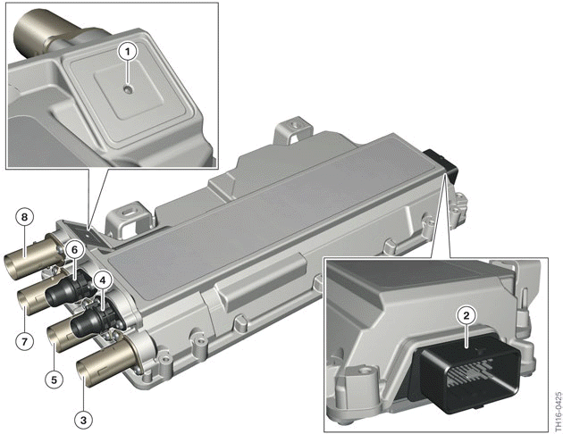
Convenience charging electronics KLE
- Ventilation opening
- Low-voltage connection/signal connection
- High-voltage connection for the electrical heating
- Coolant connection (return)
- High-voltage connection electric A/C compressor
- Coolant connection (feed)
- High-voltage connection for the Electrical Machine Electronics
- High-voltage connection charging socket
The convenience charging electronics is a high-voltage component
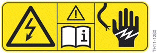
High-voltage component warning sticker
Each high-voltage component has on its housing an identifying label that enables Service employees and vehicle users to intuitively identify the possible hazards that can result from the high electric voltages used.

Only Service employees who satisfy all the prerequisites are permitted to work on the designated high-voltage components: suitable qualifications, compliance with the safety rules, procedure following the exact repair instructions.
For reasons of high-voltage safety and the warranty, the convenience charging electronics must not be opened or otherwise dismantled.
The main tasks of the convenience charging electronics are:
- Communication with electric vehicle supply equipment via a pilot line and charging plug detection line
- Actuation of the charge status indicator
- Detection of the status of the charging socket cover
- Activation of the electric motor for locking the charging plug
- Converting the AC voltage into direct current voltage (AC/DC converter)
- Supplying the electric A/C compressor with high voltage
- Supplying the electrical heating with high voltage.
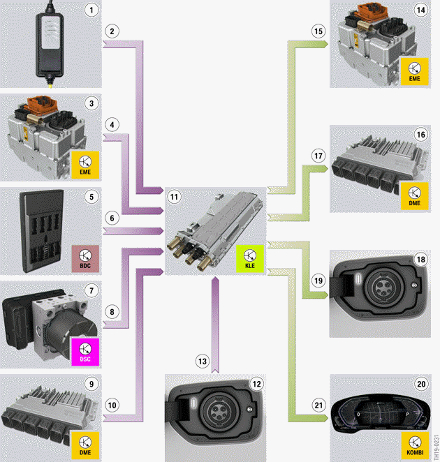
G20 PHEV, convenience charging electronics input/output
- Electric Vehicle Supply Equipment (EVSE)
- Information whether the AC voltage network is available and the charging cable is correctly connected, as well as the maximum available current level
- Electric Motor Electronics (EME)
- Requested charging power, charging voltage and charging current level (setpoint values)
- Body Domain Controller (BDC)
- Terminal status, driving readiness switched off
- Dynamic Stability Control (DSC)
- Vehicle speed
- Digital Motor Electronics (DME)
- Status of parking lock
- Convenience charging electronics (KLE)
- Charging socket
- Status of the charging socket cover and the charging plug
- Electric Motor Electronics (EME)
- Actual value of the set charging power, charging voltage and charging current level, charging release
- Digital Motor Electronics (DME)
- Information whether the charging cable is connected and the charging procedure is active
- Charging socket
- Activation of the LED for locator lighting and charging status display, activation of the charging plug lock
- Instrument panel
- Signals for the display of charging information
Communication with EVSE via pilot line and line for charging plug detection
The pilot line and charging plug detection line are realized as single signal lines. These signal lines are shielded and are terminated at a connector in the convenience charging electronics.
When charging plug is plugged into the vehicle's charging socket, this is detected by the charging plug detection line; the maximum current carrying capacity of the charging cable is also determined. An ohmic resistor is connected in the connector of the charging cable between the proximity connection and the PE conductor. The convenience charging electronics applies a measurement voltage and calculates the resistance value in the line for the charging plug detection. The resistance value specifies which maximum current level is allowed for the charging cable used (dependent on the wire cross-section). The assignment of resistance - current level is specified in the standard IEC 61851-1 ed.3.
The pilot line is required for the determination and transmission of the maximum available charging current level. The pilot signal is a bipolar rectangle signal (-12 V to +12 V). The voltage and the duty cycle are used for communicating different states between the EVSE and the vehicle:
- High-voltage electric vehicle is ready to charge (Yes/No)
- Fault present (Yes/No)
- Maximum charge current which can be provided by the AC voltage network
- Charge current
- Charging complete.
READ NEXT:
 Coordinating the charging procedure
Coordination for starting and ending the charging procedure is performed by
the high-voltage power
management in the EME.
The following actions required by the customer at the start of the charging
Actuation of the charge status indicator
The convenience charging electronics actuate the charge status indicator.
Locator lighting:
The locator lighting of the charging socket is used as an
orientation aid by the driver for the connection
Power electronics in the convenience charging electronics
The power electronics for the conversion of the AC voltage from the charging
socket to direct current
voltage, which is required for charging the high-voltage battery unit, are
housed in the conveni
SEE MORE:
Split screen
Concept
Additional information for the navigation can be
displayed in the right part of the split screen.
Switching on/off
1. Press the button on the
Controller.
2. Move the Controller to the right.
3. "Split screen".
4. "Split screen"
Selecting the display
1. Press the button on the
Controller
Introduction
The electrical machine in the G20 PHEV is a permanently excited synchronous
machine. It can convert
electrical energy from the high-voltage battery unit into kinetic energy, by
which the vehicle is driven.
Both electric driving up to approximately 87 mph (140 km/h) as well as support
o
