BMW 3: Safe working practices for working on a high-voltage system
The following description of the repair of the high-voltage components is only a general list of the content and the procedure. In general, only the specifications and instructions in the current valid edition of the repair instructions apply.

Before working on high-voltage components of the G20 PHEV, it is essential to observe and implement the electrical safety rules:
- The high-voltage system must be disconnected from the supply.
- The high-voltage system must be secured against restart.
- The safe isolation of the high-voltage system must be verified.
The following chapter provides brief descriptions on how to implement the electrical safety rules in the G20 PHEV.
Preparations
Prior to beginning any work, the vehicle must be secured against rolling away (engage the parking lock of the automatic transmission). Any charging cable connected at the vehicle must be disconnected.
The PARK vehicle condition must be established (e.g. by holding down the media button). The vehicle electrical system must also be in "Sleep" mode. This can be detected by the non-illuminated START/ STOP button.
Disconnect the high-voltage system from the supply
The high-voltage system in the G20 PHEV is disconnected from the supply with the high-voltage service disconnect ("Service Disconnect"). The color of the high-voltage service disconnect is green.
The high-voltage service disconnect is installed as a separate component in the rear right luggage compartment behind a cover in front of the power distribution box.
To disconnect from the supply, the connector must be pulled from the relevant socket. The circuit of the high-voltage interlock loop is interrupted and the high-voltage system is disconnected from the supply. In addition, the voltage supply of the switch contactors is also interrupted.
When closing the high-voltage service disconnect (recommissioning) it is necessary to ensure that a lock does not prevent this mechanically. Therefore, the lock must be mechanically unlocked with a tool in order to push together the connector and socket of the high-voltage service disconnect. By doing this the circuit of the high-voltage interlock loop is closed again and the supply of the electromagnetic switch contactors is re-established.
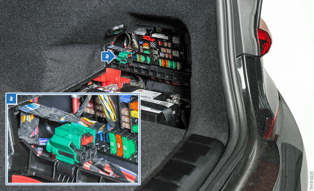
G20 PHEV: high-voltage service disconnect

To pull apart the socket and the connector, the red mechanical lock shown in the image must be removed.
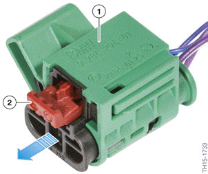
As soon as the lock (2) has been removed, the connector can be pulled a few millimeters out of the socket(1).
Do not pull any further or harder if resistance can be felt. The connector and socket of the high-voltage safety connector cannot be disconnected from each other completely.
Provide the high-voltage system with a safeguard against unintentional restarting
Securing against restart is also effected at the high-voltage safety connector. A commercially available U-lock (for example ABUS 45/40) is required for this purpose.
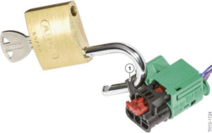
By separating the socket and connector of the high-voltage service disconnect, a bore hole (1) through both parts becomes free. The loop of a typical U-lock must be inserted in this bore hole.
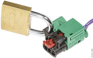
The U-lock can now be closed. The key must be stored in a safe place during work on the high-voltage system so that an unauthorized person cannot unlock the lock.
The connector can no longer be used by inserting and closing the U-lock at the high- voltage safety connector. This is an effective way of ensuring that the high-voltage system is not switched on again without the knowledge and consent of the Service employee.
Establish that the system is isolated from the power supply
The de-energized state is not verified using a measuring device in the BMW Service workshop.
Instead, the high-voltage components measure the voltage themselves and transmit the measuring result via bus signal to the instrument cluster.
The instrument cluster does not generate the Check Control message to display the de-energized state unless all involved high-voltage components consistently signal the de-energized state. This Check Control symbol in red shows a crossed-out flash symbol. The text message "High-voltage system deactivated" also appears.
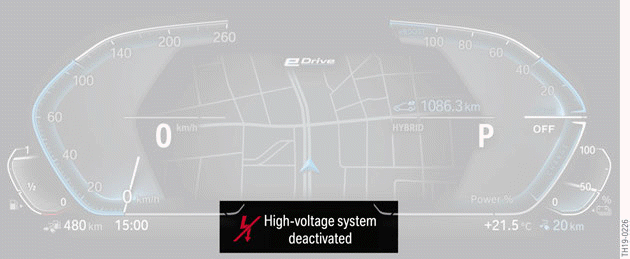
G20 PHEV, Check Control symbol "High-voltage system deactivated"
In order to verify the de-energized state, the service technician must switch on PAD mode and wait until they see the Check Control message with the symbol shown above on the instrument cluster.
Then, and only then, have you ensured that the high-voltage system is de-energized. After verifying the de-energized state, the PARK vehicle condition must be re-established before starting with the actual work.
Alternatively, there is the option to determine the de-energized state with the ISTA workshop system.
If the CC message is not displayed, the "Disconnect high-voltage system from the power supply: Read out reasons" service function can be carried out. If the de-energized state also cannot be clearly established with this service function, work cannot be carried out on the high-voltage components Before commencing work the de-energized state must be established by a certified qualified electrician (1000 V DC) using corresponding testers/test procedures.
Then the vehicle must be labelled with the corresponding warning stickers. These signs serve for easier and uniform identification of electric vehicles. Their role is to make the individual statuses of the high-voltage system of a vehicle clearly visible for everyone in an instant. These warning stickers and their handling are provided in the ISTA workshop system in the repair instructions "Note on the identification of the high-voltage system" (REH-HIN-P-6125-24).
READ NEXT:
 Procedure after an accident
The safety concept of the high-voltage system ensures that, even during or
after an accident, there
is no danger to the customer, the rescue services or the service employee. The
high-voltage system
Designation and identification
Designation of electrical machines
The electrical machine designation is used in the technical documentation for
clear identification of
the electrical machine. However, the identification of the ele
Design
The main components of the electrical machine are:
Rotor and stator
Connections
Rotor position sensor
Cooling
The hybrid system in the G20 PHEV is a so-called parallel hybrid system. Both
SEE MORE:
Integrated Owner's Manual
in the vehicle
Concept
The Integrated Owner's Manual specifically describes
features and functions found in the vehicle.
The Integrated Owner's Manual can be displayed
on the Control Display.
Selecting the Owner's Manual
1. Press the button.
2. "CAR".
3. "Owner's Manual".
4. Select the desired method of access
General driving notes
Closing the trunk lid
Safety information
Warning
An open trunk lid protrudes from the vehicle
and can endanger occupants and other traffic
participants or damage the vehicle in the event
of an accident, braking or evasive maneuvers.
In addition, exhaust fumes may enter the car's
interior. There is
