BMW 3: Cooling
The Electrical Machine Electronics and convenience charging electronics (KLE) are cooled by the low- temperature coolant circuit.
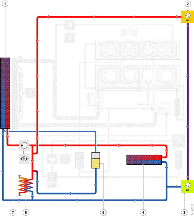
G20 PHEV, low-temperature coolant circuit (schematic diagram)
- Radiator (coolant/air heat exchanger)
- Electric Motor Electronics (EME)
- Convenience charging electronics (KLE)
- Integrated indirect charge air cooler (air-coolant heat exchanger)
- Coolant expansion tank
- Coolant-based air conditioning condenser (coolant-refrigerant-heat exchanger)
- Electric coolant pump
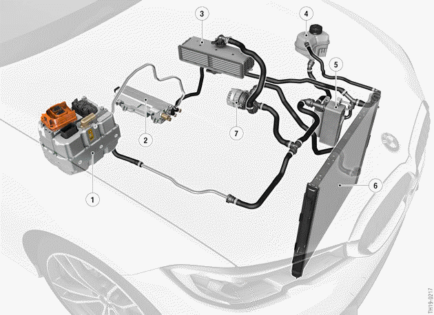
G20 PHEV, installation locations of the low-temperature circuit-coolant
circuit
- Electric Motor Electronics (EME)
- Convenience charging electronics (KLE)
- Integrated indirect charge air cooler (air-coolant heat exchanger)
- Coolant expansion tank
- Coolant-based air conditioning condenser (coolant-refrigerant-heat exchanger)
- Low-temperature coolant radiator (air-coolant heat exchanger)
- Electric coolant pump (130 W)
The low-temperature coolant radiator (air-coolant heat exchanger) is integrated in the cooling module.
Depending on the cooling requirement of the Electrical Machine Electronics, the electric coolant pump and the electrical fan are activated according to requirements thus contributing to a reduction in consumption levels.
Thanks to the demand-driven activation of the electrical fan and electric coolant pump, large temperature deviations which would have a negative effect on the service life of the electronics are avoided and energy-optimized cooling is achieved.
There is no electrical fill level sensor installed in the expansion tank. But the following special feature should be noted for Service: A loss of coolant, for example due to a leak, in the cooling system is not identified directly due to the lack of an electrical level sensor. Instead, with a loss of coolant the temperature of the Electrical Machine Electronics will rise above the normal operating range. In this case the power of the Electrical Machine Electronics is reduced and a corresponding Check Control message is issued. The Service employee must check the following fault causes during troubleshooting:
- Loss of coolant, e.g. by a leak
- Incorrect low-temperature coolant radiator
- Electric fan does not work or is restricted
- Incorrect coolant pump
- Coolant lines or connections damaged
- Incorrect component to be cooled (e.g. EME).

If excess temperature is displayed in the cooling system, then this may have several causes, including also the loss of coolant. Therefore, during troubleshooting all components of the cooling system must be checked systematically.
While the high-voltage battery unit is being charged, the power electronics in the EME is working.
Due to the huge electrical power which is transformed in the EME, heat also arises. This must be dissipated using the cooling circuit described here. Therefore, the electric coolant pump and the electric fan may also run during charging at a correspondingly high temperature in the EME.
No work may be carried out at the vehicle during charging mode. The charging cable must be disconnected from the vehicle before starting work. The coolant pump and the electric fan can be switched on automatically when charging the high-voltage battery unit. Therefore, the high-voltage battery unit may not be charged when working at the vehicle.
The activation of the coolant pump and electric fan can be effected in the following vehicle conditions:
- Vehicle condition DRIVE exists
- PAD mode is activated
- High-voltage battery unit is being charged
- Preheating/precooling is active
When PAD mode is activated, the power-electronics circuits of the Electrical Machine Electronics are already functional. In this way, both the high-voltage electrical system (EKK and electrical heating) and the 12 V vehicle electrical system are supplied with energy by the DC/DC converter. If due to the rising heat a cooling requirement is identified, the coolant pump is switched on, and if required also the electric fan.
READ NEXT:
 Antifreeze and corrosion inhibitor
The cooling system of the G20 PHEV is filled with the new antifreeze and
corrosion inhibitor Frostox
HT-12. The new antifreeze and corrosion inhibitor increases the long-term
stability and corrosion
Overview
With the G20 PHEV the already familiar Generation 4.0 high-voltage battery
unit with the designation
SP41 is used. The lithium-ion battery has the same basic design as the
Generation 3.0 SP06 high-
SEE MORE:
Warning with braking function
Display
If a collision with a pedestrian or a cyclist is imminent,
a warning symbol appears on the instrument
cluster and in the Head-up Display.
The red symbol is displayed and a
signal
sounds.
Alternatively, depending on the
vehicle
equipment, a red warning triangle lights
up in the instrument
What must be observed when charging the high-voltage battery unit?
It is not permitted to simultaneously charge the high-voltage battery
unit and fill the fuel tank
When the charging cable is connected, do not fill the fuel tank and keep a safe
distance from highly
flammable materials. Otherwise, in the event of an improper connection or if the
charging cable
